Call Us Today: +90 232 765 9151
[email protected]
[email protected]

MkaPEB's capabilities
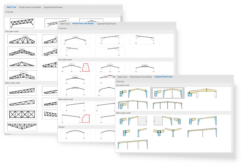
A- Fast modeling with template structure types
MkaPEB has a wide range of template types defined for portal frame and steel roof truss systems with variable cross-section. All the features of the roof systems in these templates are parametric. If needed, they can be defined side by side and in different levels.
B-1. Automatic load analysis according to EN-1991 and ASCE-07-16 - WIND LOADS
Wind loads are calculated based on EN-1991-1-4 and ASCE-07-16 standards. MkaPEB users can found national annexes for Turkey as well as for European Union countries in order to make a project in Germany, Austria, Belgium, Bulgaria, Denmark, France, Croatia, Italy, Ireland, England, Sweden, Cyprus, Norway, Poland, Portugal, Romania, Slovakia, Slovenia, and Greece.
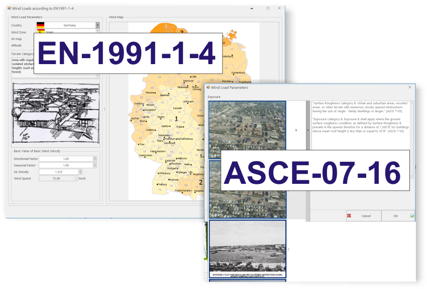
After the wind related parameters are taken from the regulations, the distributed loads coming to the roof and facades of the structure are calculated automatically.
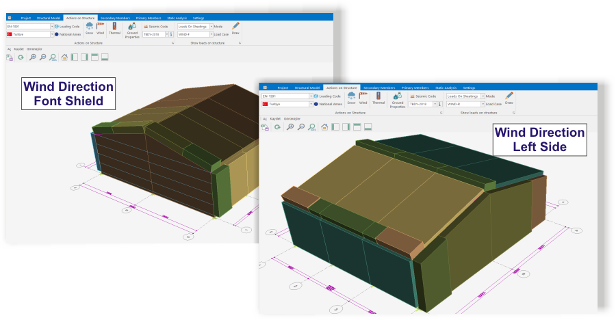
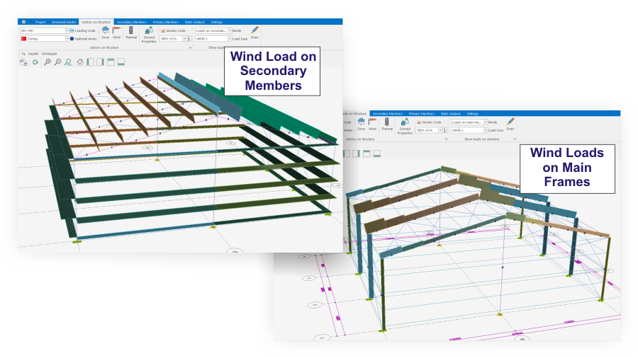
The loads coming to the roof and facades are automatically transferred to the roof and wall purlins and then to the main carrier system.
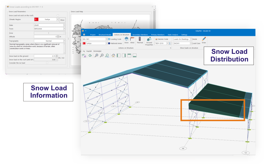
B-2. Automatic load analysis according to EN-1991 and ASCE-07-16 - SNOW LOADS
One of the biggest problems when calculating snow loads is the amount of snow accumulated in between, especially when roof systems are at different elevations. The calculation methods are given in EN-1991-1-3 and ASCE-07-16 for the load increase due to snow accumulation.
MkaPEB knows the relative position of the roof systems. Apply the rules specified in the regulations related to snow loads and calculate the loads affecting the structure.
We all know that to TS-EN 1991-1-3 snow load values given in Turkey is insufficient for many regions. In order to eliminate this situation, we consider that the ice load with a density of 900 kg / m3 and 3-5 cm ice is in place.
B-3. Analysis of earthquake loads
TDY-2018, AISC-341-16, Eurocode-8, EAK-2000 (Greece) Earthquake regulations in MkaPEB. The reason that the structure is regular, single storey and the first period is always the dominant period is calculated according to "Equivalent Seismic Load Method".
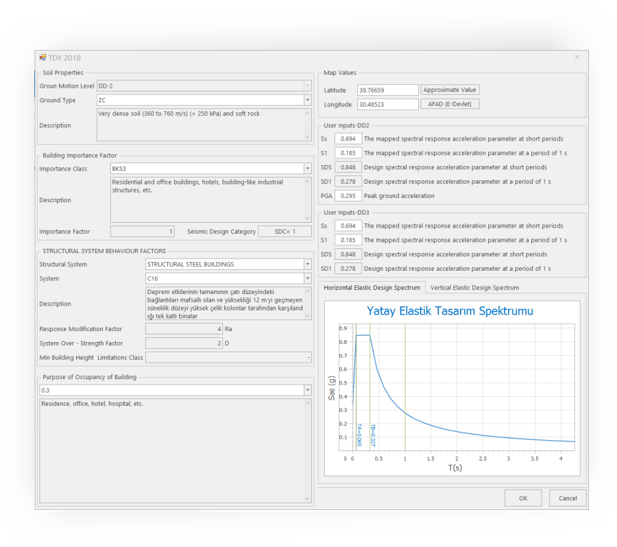
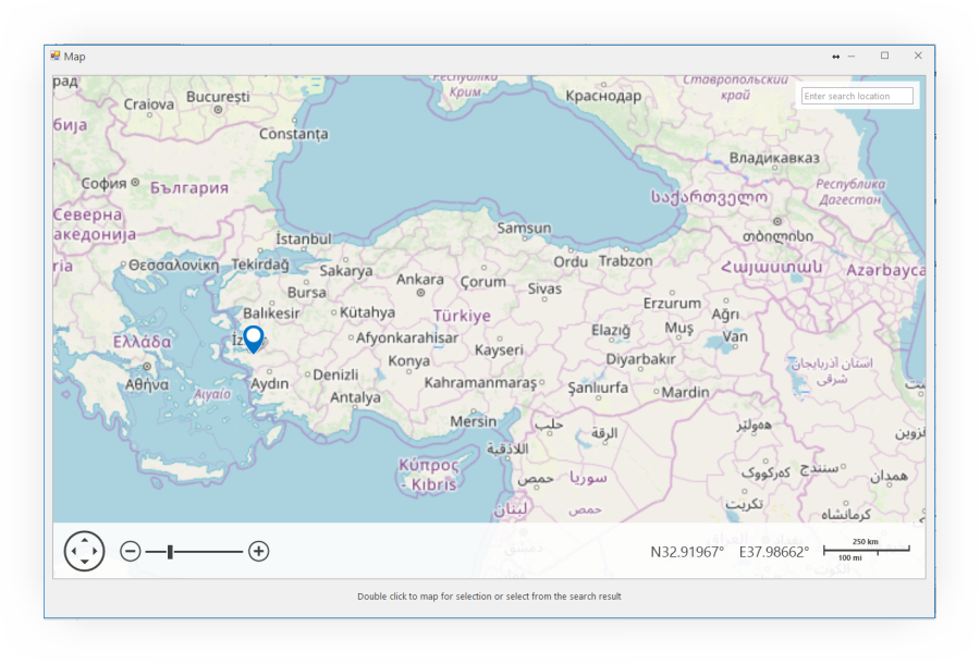
TDY-2018 and AISC-341-16 require some parameters to be taken on the map in the calculation of earthquake loads. The values to be read from the map for AISC-341-16 are obtained on the given webservice. For TDY-2018, this information can be retrieved by entering e-government password to AFAD's system and it can be obtained without entering AFAD's system with 2/1000 difference from the map in MkaPEB.
C- Static analysis and design of bar elements
While the structural analysis of the steel structure is carried out, the main structural system and secondary structural elements are involved. Secondary structural elements such as roof, wall, wind column, intermediate secondary beam, crane walkway transfer the loads they receive from the pavements they are related to to the main carrier system. For this reason, the design of the secondary structural elements are made priorities and then the analysis and design of the main carrier system is carried out.Eurocode-3, CYTHYE-2016, AISC-360-10 and AISC-360-16 standards can be used for the design of steel structure elements in MkaPEB. Since there is no detailed calculation method for the light steel construction elements preferred for use in roof and wall purlins within the new steel structures regulation, these elements are designed according to Eurocode-3-1-3 at MkaPEB.
C-1.1 Design of secondary structural elements - ROOF PURLINS
As we have shown in the load analysis section, there are regional differences when wind and snow loads (due to snow accumulations) transfer loads to the roof planes. Therefore, each roof plane is considered separately. The analysis page has two separate controls, up and down. In the downward control, the dominant load is snow, while the upward direction is wind. These analyzes were carried out considering that there may be regions with low snow loads and high wind loads.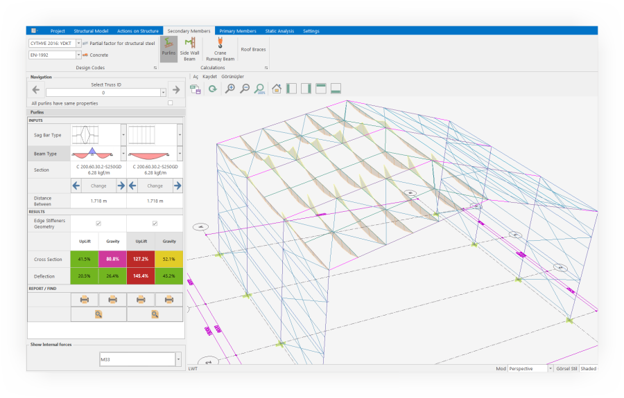
C-1.2 Design of secondary structural elements - SIDE and SHIELD WALL PURLINS
They are the structural elements that transfer the loads coming from the coating on the side walls to the main carrier system. Wind, coating core, purlin is calculated by taking into account their own loads. The critical question here is the wind load. Wind loads from left, right, front and rear affect this structure. As you can see in the section on load analysis, these loads vary according to the geometry of the structure and the wind direction. MkaPEB checks each purlin separately according to the load combinations created for all wind loads.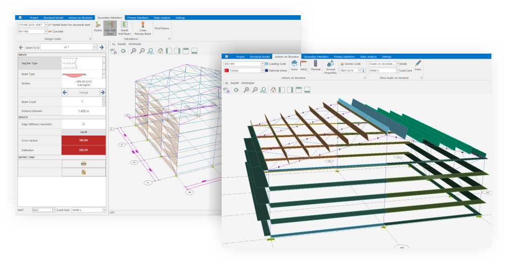
C-1.3 Design of secondary structural elements - GANTRY CRANE WALKING PATHS
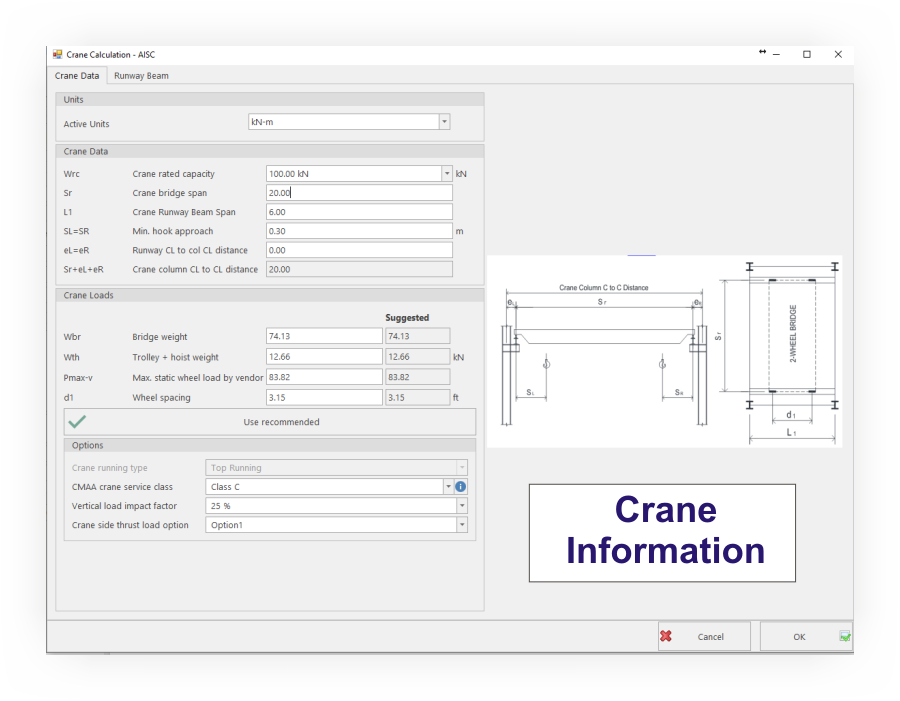
Gantry cranes are widely encountered in industrial buildings such as warehouses and factories for horizontal and vertical transport. At MkaPEB, the design of paths of gantry cranes and reaction forces to the columns are used in the analysis of the main carrier frame system.
The biggest problem when designing gantry crane paths is that the weight of the crane bridge and the cat cart and the distance between the wheels vary according to the manufacturer. In MkaPEB, the approximate values for these unknowns can be taken from our real values, no matter how much they are given to them.
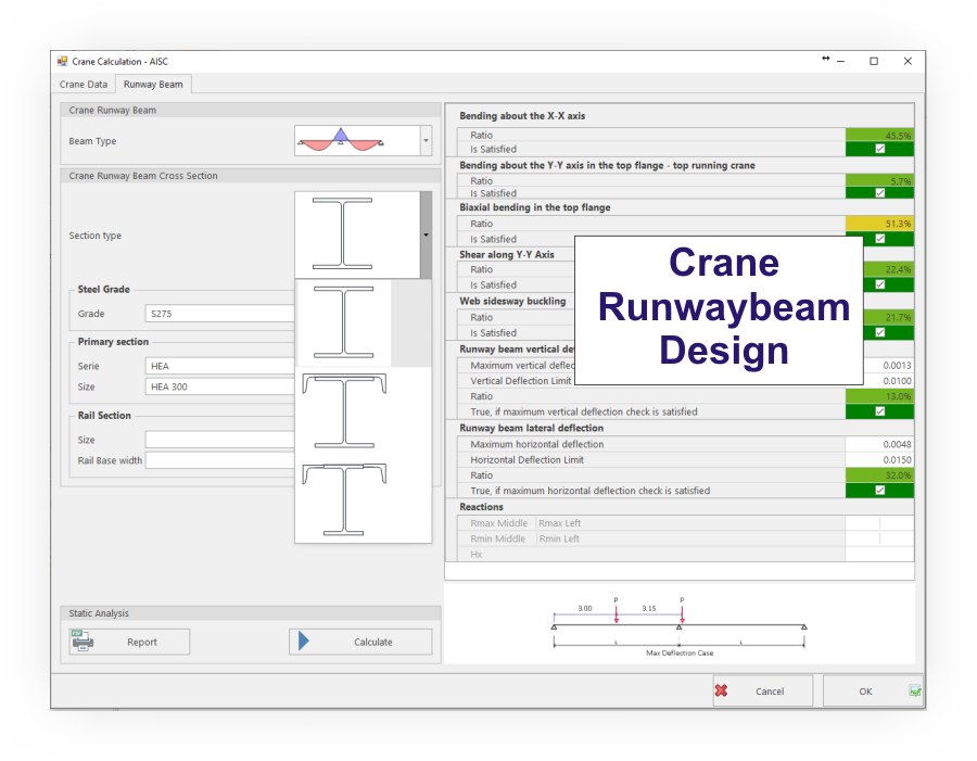
Especially in cranes with high lifting capacity (more than 30 tons), horizontal displacement is a problem in crane walkway. The main reason for this situation is that only the head of the H beam, which is used as a walkway, is taken into account in the weak direction. In practice, it is sometimes the only solution to close the U profile on the H profile we encounter from time to time, or to increase the inertia of the head with angles.
The biggest problem when designing gantry crane paths is that the weight of the crane bridge and the cat cart and the distance between the wheels vary according to the manufacturer. In MkaPEB, the approximate values for these unknowns can be taken from our real values, no matter how much they are given to them.
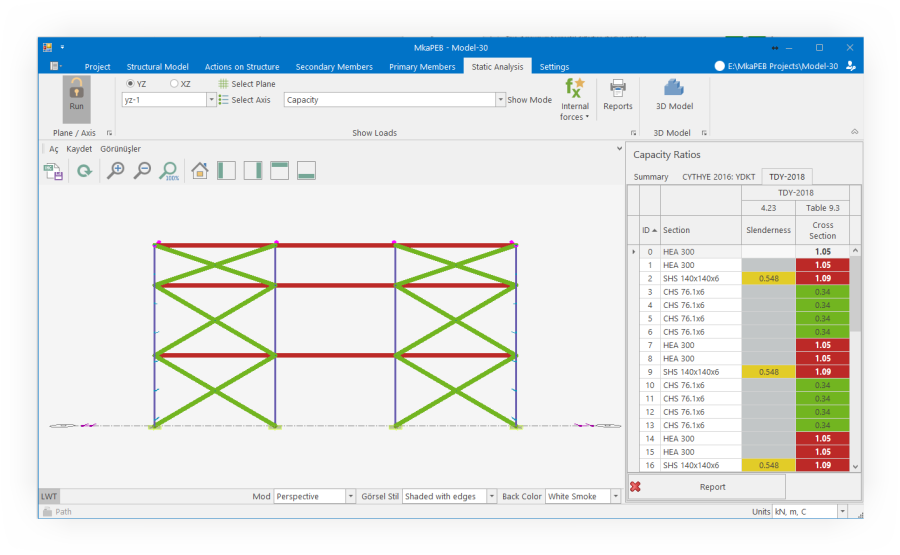
C-2.1 Design of main structural elements - YZ AXLES (Vertical direction to steel scissors)
In the direction perpendicular to the steel shear, the steel columns are connected by stability crosses. If the structure is long, it is possible to define a dilatation gap in MkaPEB. Due to seasonal temperature changes, the structure is shortened and elongated. In Turkish regulations, there is no clear statement about how many meters a thermal dilatation gap will be left in steel structures. In an article about Eurocode-3, it is stated that if the length of the building exceeds 60 meters, either a thermal dilatation gap will be made or the effects arising from the temperature difference will be taken into consideration in the analysis. At MkaPEB, temperature differences are taken into account in all circumstances.Particularly in central crossed systems, because of the high rod length, the slender conditions cannot be exceeded in the pressure-operated rods. While analyzing the YZ axes, the pressure from the central diagonals was removed from the system as if they were never used.
The static analysis of the YZ axes and the design of the stability beam and cross members connecting the columns are not only related to the tensile force in steel structure regulations but also to the conformity of the slenderness and cross-sectional dimensions in the earthquake regulations.
C-2.2 Design of main structural elements - XZ AXLES (Steel shear line)
Loads from the secondary structural elements shall be carried by the main carrier systems. This load transfer is done by MkaPEB. XZ axes are grouped by comparing the number of bars, number of joints, overhead crane and spacing, and static analysis is performed for the axles with the most negative loads. In the design of the bars and joint joints, the required load combinations are automatically generated by considering the loads acting on the structure as specified in the selected standards.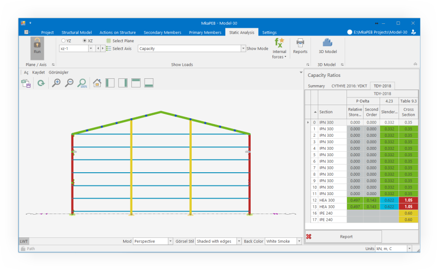
E- Detailed account report preparation
Today, the most common method of accounting report preparation is to give the results in tables. Since the civil engineer who prepared the project in such reports cannot control the accounts step by step, the program has no choice but to trust the producers. If there is a faulty transaction and/or calculation, it must be determined and corrected by someone else.MkaPEB prepares detailed reports that show you step by step how snow, wind and earthquake loads are obtained, how the bar elements and joint calculations are made.
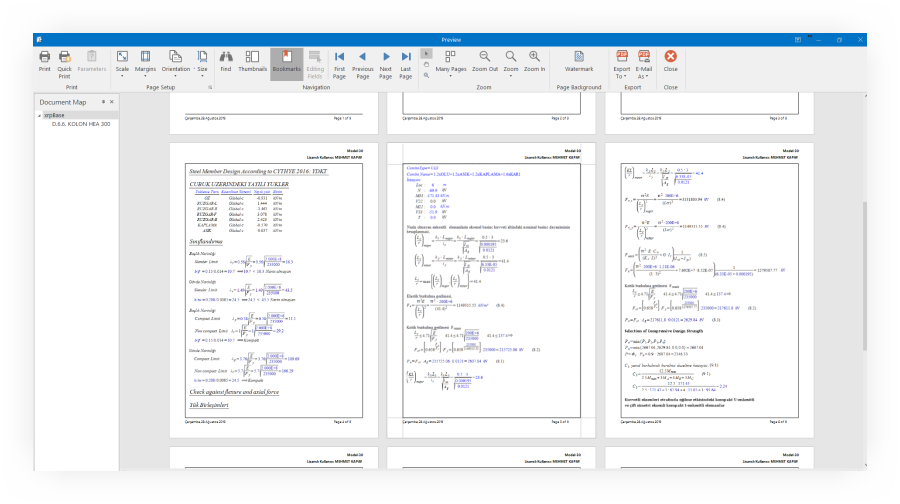
Sample account reports
Within MkaPEB, there are many regulations regarding the loads that affect a large number of structures, the earthquake regulations and the accounting rules for steel structures. Our goal here is that you can make projects abroad before MkaPEB is used abroad. Our program can also prepare English versions of detailed account reports that you can see above.A- PEB (Pre-Engineered Building) type structures
Variable H section frames are 25% lighter than gantry frames made of normal rolled steel. This ratio increases as the frame opening increases. You can access the articles written in this topic.
PEB & Type: 508
The following video shows how to create a 3D model of MkaPEB and PEB type 508.
PEB & Type: 509
MkaPEB and PEB type 509 type curtain wall is used in a building, the size of the parametric changes and 3D solid model is created below the video is created.
B- Portal frame type structures
H-shaped rolling steel columns and beams are widely used in these structural systems, CNC machines can be produced quickly because it is the first choice of many manufacturers.
Portal frame & Type: 101
Type 101 is used in this video.
Portal frame & Type: 101
Type 101 is used in this video.
Multiple roof systems & Type-101 + Type-108 + Type-105
A -Manufacturing drawings (singular and assembly part drawings)
DSTV-NC files were prepared in order to be able to cut steel plates with CNC plasma and profiles with CNC profile drilling machines in the pre-manufacturing stage of the steel structure production processes and individual parts drawings were obtained in the contents of the files.
Type 105 is used in this video.
Portal Frame & Type: 105
With MkaPEB, it is shown how static analysis and technical drawings of a structure using Type 105 of portal frame type structures are obtained.